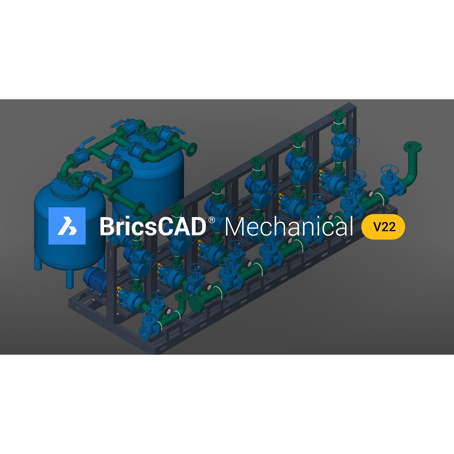
BricsCAD® Mechanical


Couldn't load pickup availability
Familiar and compatible CAD
BricsCAD is built entirely on the industry standard DWG format, with full command, script, macro, and menu compatibility. BricsCAD feels like home!

Intelligent mechanical design
BricsCAD makes advanced mechanical design accessible, intelligent, flexible, and affordable, enabling greater design freedom.
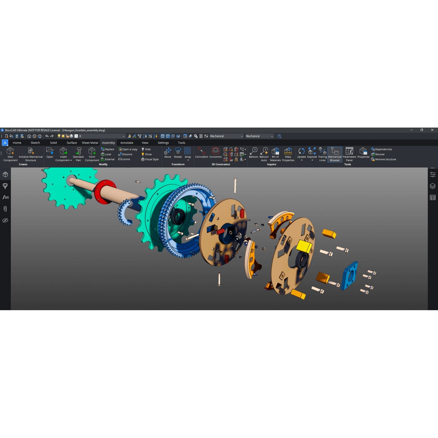
Design parts and components
With BricsCAD Mechanical, the design process is simple. Start your design with a 2D sketch, then extrude, revolve or sweep it to create a 3D solid. You can also use built-in 3D primitives to specify the initial shape of your part. Move on to the details using extrusions, fillets, chamfers, Boolean operations, and edit using dynamic direct modeling. You control as much or as little of the form as you like with parameters. You can also import 3D solids and edit them as native components.
BricsCAD’s unique variational 3D modeling approach gives you the freedom to design how you want to, from concept to detail, with whatever level of parametric control you need. Quickly develop complex stand-alone components or directly within an assembly.
Import or create from scratch
BricsCAD Mechanical can create sheet metal components from scratch and allows users to automatically convert solid parts to sheet metal with just one click. This robust approach lets you spend more time evolving your design and less time worrying about redefining sheet metal features.
Rework at any time
Sheet metal parts can be edited with the full power and freedom of direct modeling, while the consistency of each feature (flanges, bends, reliefs, junctions) is automatically maintained.
Automatically unfold
Create un-folded 2D representations that are bi-directionally associated to the 3D sheet metal part. You can also use the unfolding engine to send parts to industry-standard CAM systems.
Feature-based direct modeling
The flexibility of direct modeling maintains design intent, expressed as sheet metal features – flanges, bends, reliefs, and others.
Convert to sheet metal
3D models created in BricsCAD or other CAD systems can be converted to sheet metal automatically, with one click. Features can then be manually refined or changed to quickly achieve your desired form.
Unfolding
Create 2D and 3D unfolded representations to drive CAM systems. The 3D unfolded representation can be edited simultaneously to fix detected conflicts, while keeping the 3D folded part in sync.
Parametric sheet metal parts
Use the full power of 3D constraints, arrays, and automatic parametrization to create different design variants from your sheet metal models.
Hems
The hem feature for Sheet Metal allows you to model a hemming metal-working process. BricsCAD supports open hems, teardrops, and rounds with user-adjustable parameters.
Form features
BricsCAD Mechanical provides a library of parametric form features – such as louvers, bridges, embosses and others. You can also create complex ribs defined by any curve.
Lofted bends
You can create lofted sheet metal parts between two arbitrary 3D curves. BricsCAD Mechanical can recognize lofted bends in imported geometry and automatically decompose them into multiple flanges.
Flanges, bends, junctions, and tabs
Create flanges in multiple ways: using a base flange, an edge flange or a via a contour tool. You can always change the way adjacent flanges connect – via a bend, a junction or a tab-and-slot connection – to improve manufacturability.
Reliefs and Splits
Avoid material conflicts during the bending process by leveraging the library of reliefs in BricsCAD Mechanical. Split parts in a single click, and automatically propagate the split to other corners in your model.
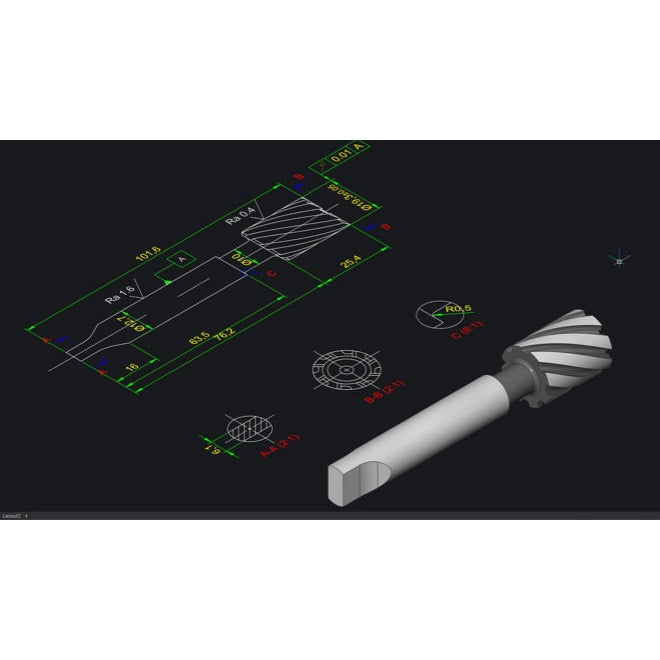
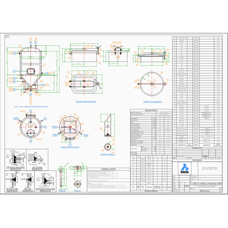
Efficient 2D detailing
BricsCAD offers the best and most familiar workflow for turning your mechanical designs into production drawings.
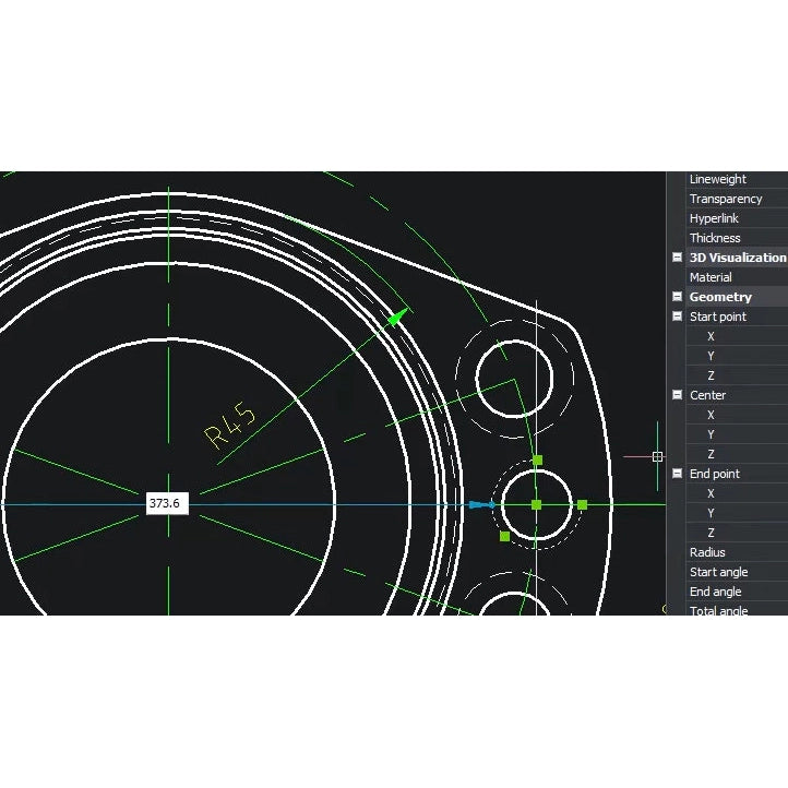
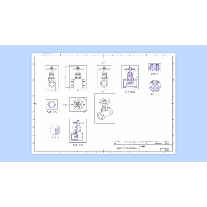
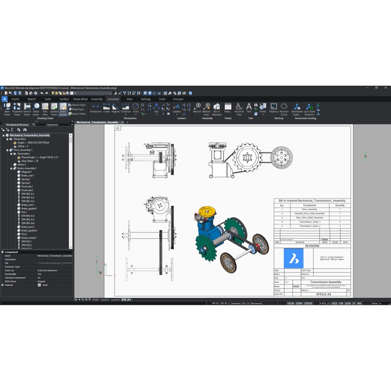
Drawing views
Automatically create drawing views of your 3D parts and assemblies and detail views easily with dimensions and annotations. If your 3D model changes, generated drawing views are updated automatically.
- Base views
- Projected views
- Section views
- Detail views
- BOM table
- Balloons
Fast generation of draft-quality drawings
Speed up drawing layout using fast, draft-quality views and use multi-core CPUs to create detailed views in record time. BricsCAD Mechanical is responsive to your inputs during background drawing generation.
Automatic drawing update
Drawing views remain associated with the 3D model. Change a single part, subassembly, or the whole assembly, and all 2D drawing views are automatically updated, allowing fast design iterations and changes.
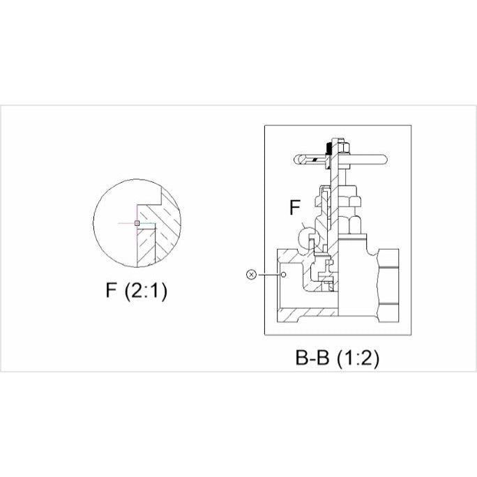
Section views
You can create section views of 3D parts and assemblies. Section planes can be defined by a line drawn on a base view, or you can create more complex sections: half sections, offset sections, and aligned section views.
Detail views
BricsCAD Mechanical allows you to automatically create detail views from any existing view in your drawing layout.
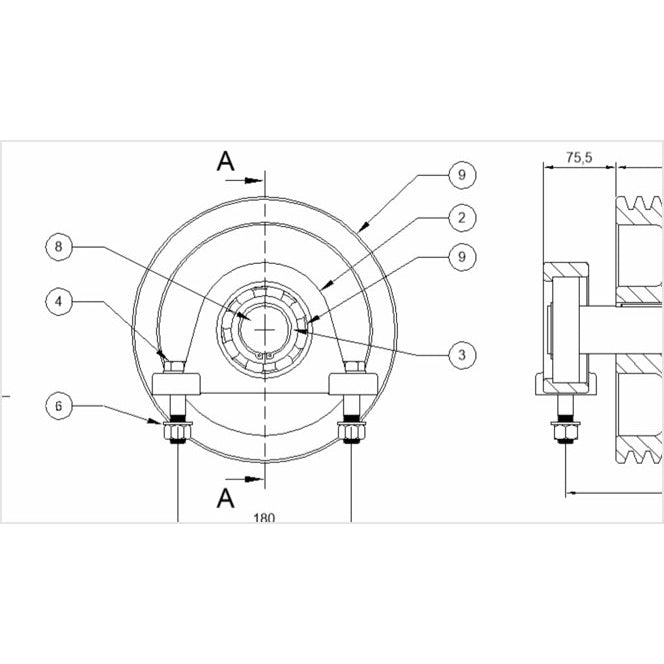
Bill of Materials table
The BOM panel lets you manage multiple BOM tables in your drawings. You can format each column individually, set up equations, sort tables, and more.
Balloons
BricsCAD Mechanical creates associative balloons for each component in an assembly and manages the display of those tags in all automatically generated 2D views.
Mechanical symbols and annotations
All the 2D detailing annotations you need, from datums and geometric tolerances to surface finishes to weld symbols and representations, are available at your fingertips to quickly create 2D production drawings.
Power Dimensions
The POWERDIM tool intelligently creates the right dimension for the selected geometry, including fits and tolerances, making dimensioning your drawing views effortless.
AutoCAD® Mechanical compatibility
Easily open, edit, and reuse symbols and annotations in your drawings created in AutoCAD Mechanical.
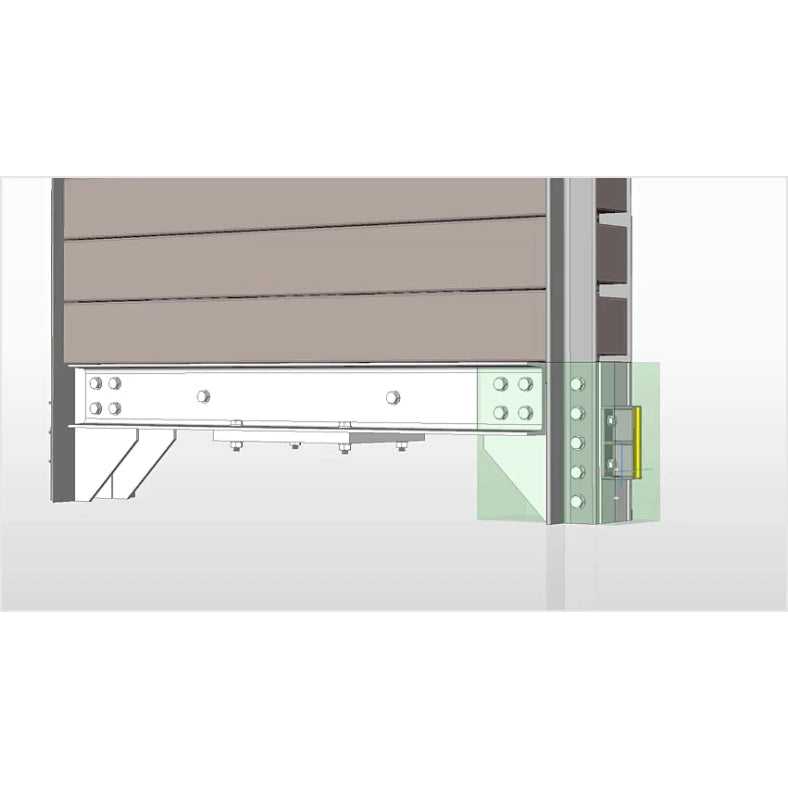
Multi-CAD Connectivity
Bring CAD data from many other formats seamlessly into BricsCAD with Communicator for BricsCAD. Easily and quickly build it into your assemblies, modify it via direct modelling, or make it intelligent by applying parameters.
Import and export all types of files with BricsCAD
Available by default in BricsCAD:
- DWG/DXF/DWT
- SketchUp® (import)
- ACIS SAT
- Images (TIFF, JPEG, etc.)
Communicator for BricsCAD®
A BricsCAD add-on to seamlessly import 3D geometry and PMI data from all major CAD applications.
- Import and export other file formats for:
- Parasolid
- Inventor®
- SOLIDWORKS®
- Catia™
- STEP
- Siemens NX
- Creo
- IGES
Documents
Documents
$0.00 CAD